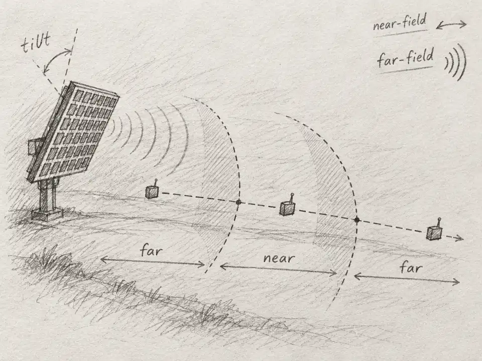
Imagine walking toward a wireless access point mounted above the street. The familiar expectation is that the signal’s character changes once: far away, it behaves like a broad, nearly flat wave; closer in, the curvature of the wavefront matters. Keep walking, and you cross from one region into the other.
A new analysis of future terahertz links finds that this tidy boundary can fold back on itself. Under some realistic arrangements, a moving receiver can pass through the far field, enter the near field, then return to the far field. The surprising part is not that the signal reverses direction. It is that the dividing line between two ways of describing the signal can shift as the receiver moves.
The study, by Peng Zhang, Hanmei Yuan, Zhe Wang, Vitaly Petrov, and Emil Björnson, examines an access point with a downward-tilted antenna array and a receiver traveling along the ground. The authors derive when the unusual pattern can occur for two array designs: a uniform linear array and a uniform planar array. Their results are mathematical and numerical, not a report of a field test. They show why future wireless-system designers may need more than a single distance to characterize a link.
To see why, picture the antenna array as a row or panel of tiny radio-wave sources. Far from the array, the wavefront reaching the receiver is close enough to flat that engineers can often model it as a plane wave. Nearer the array, the wavefront’s curvature across the antenna elements becomes important. The signal’s phase—the timing of its oscillations—varies across the array in a way that a flat-wave approximation can miss.
That distinction matters for large arrays and short wavelengths. Terahertz frequencies, spanning 300 GHz to 3 THz, are being studied for future high-capacity wireless links. At these frequencies, an array can be large compared with the wavelength even when it is compact by everyday standards. Engineers may need to account for the curved wavefront over distances that would seem far away in ordinary experience.
But near-field boundaries are not simply painted circles around an antenna. The paper uses a phase-error criterion: if the phase variation across an array exceeds a chosen threshold, the link is classified as near field; below it, the far-field approximation is considered adequate. Crucially, that variation depends not only on separation but also on the angle at which the receiver views the array.
Now add the geometry of a street. The access point sits above the receiver and points its array downward. As the receiver moves along level ground, its distance from the access point changes, but so does its angle relative to the antenna. Those two changes pull on the phase-error boundary at the same time. The boundary can therefore approach the receiver, pass it, and then shift again—creating two crossings rather than one.
The authors work out the conditions for this behavior and calculate examples using a 300 GHz carrier, a 0.1 m antenna aperture, a receiver height of 1.5 m, and a downward tilt of 12 degrees. In one example, a linear array at an access-point height of 5 m shows the far-near-far pattern. A planar array shows it at 24 m. The array design matters: at 15 m, the example planar array instead has a conventional near-to-far transition, while the linear array remains in the far field over the range shown.
Those numbers are not measurements from a street installation. They are examples generated from the authors’ model, using a standard phase criterion. That distinction is important: the paper does not claim that every person walking beneath a future 6G antenna will experience a visible or abrupt change in service. The far-field and near-field labels describe which wave model is appropriate, not two sharply separated zones that a phone can sense as a switch.
The analysis also finds that the effect is not confined to the most extreme terahertz frequencies. In the examples, two transition points can appear across a range below 300 GHz as well. The precise locations, and whether the double crossing occurs at all, depend on array size, access-point height, tilt, frequency, and the shape of the array. The far-near-far window is generally wider for the linear array than for the planar array in the scenarios examined.
That is where the result becomes useful. A network planner might otherwise treat the near-field boundary as one fixed radius and assume that moving closer always means moving deeper into the near field. For a tilted array serving ground-level users, the paper shows that assumption can fail. Modeling the angle as well as the distance could help engineers choose antenna placement and tilt, and decide where plane-wave approximations are reliable.
There is no contradiction in a receiver getting physically farther away while its link enters the near field. The distance from the access point increases steadily along the paper’s ground-coordinate path; what changes non-monotonically is the comparison between that distance and an angle-dependent boundary. The path through space is straightforward. The geometry of the wavefront is not.
In a future wireless network, the most important question may not be simply how far the receiver is from the antenna. It may also be which part of the antenna the receiver is facing—and at what angle. In this analysis, a signal’s field classification turns out not to be a one-way journey inward. Under the right geometry, it can cross the line, cross back, and make the map of a wireless link more interesting than a circle around a tower.